Luoyang Anjing Intelligence Equipment are a global leader in high-temperature electric furnaces



How to Improve Temperature Uniformity in an Industrial Furnace
To improve temperature uniformity in an industrial furnace, optimize heating-element distribution, use multi-zone temperature control, improve insulation and furnace sealing, position loads correctly, and calibrate thermocouples regularly. Large or deep chambers may require multiple independently controlled heating zones to minimize hot and cold spots.
I. Introduction
Temperature uniformity in industrial furnaces is critical for high-temperature processes such as heat treatment, sintering, annealing, and calcination. When furnace temperatures are uneven—resulting in “cold spots” and “hot spots”—product quality becomes inconsistent, production cycles are extended, and the rate of defective parts increases.
Simply increasing the furnace’s power output will not solve the problem. Temperature uniformity depends on a variety of factors: the arrangement of heating elements, the use of multi-zone temperature control, the placement of thermocouples, the quality of thermal insulation, the geometry of the furnace chamber, the distribution of the load, atmosphere circulation, and PID control. Below, we will explore, step by step, how to identify temperature variations and improve overall temperature uniformity.
II. What Is Furnace Temperature Uniformity?
Furnace temperature uniformity describes how evenly temperature is distributed throughout a defined working zone inside the furnace.
For example, if a furnace is operating at a target temperature of:1000°C
but measurements at different locations show:
- Point A: 995°C
- Point B: 1001°C
- Point C: 1004°C
- Point D: 998°C
then the actual temperature field is not identical at every point.
In industrial heating, the objective is usually not to make every physical point mathematically identical. Instead, the goal is to maintain the qualified working zone within the temperature-uniformity tolerance required by the process.
This distinction is important:
Temperature control accuracy ≠ temperature uniformity
Temperature control accuracy describes how accurately the control system maintains the temperature measured at its control point.
Temperature uniformity describes how evenly temperature is distributed across the usable furnace volume.
A furnace can therefore have highly accurate PID control at one thermocouple while still having hot or cold areas elsewhere in the chamber.
1.Why Is Temperature Uniformity Important?
Poor furnace temperature uniformity can directly affect product quality.
Depending on the application, temperature differences may cause:
- Uneven heat treatment
- Inconsistent hardness
- Incomplete sintering
- Uneven grain structure
- Product deformation
- Surface defects
- Different shrinkage rates
- Inconsistent material properties
- Increased scrap rate
- Reduced process repeatability
Temperature uniformity is particularly important for:
- Tool and mold heat treatment
- Alloy heat treatment
- Ceramic sintering
- Powder metallurgy
- Electronic ceramics
- Semiconductor materials
- Battery materials
- Technical ceramics
- Annealing
- Tempering
- Calcination
- High-temperature laboratory processes
For these applications, furnace selection should consider not only maximum temperature, but also the required uniform working zone.
2.What Causes Uneven Temperature in an Industrial Furnace?
Before trying to improve furnace uniformity, identify the source of the temperature difference.
Common causes include:
- Poor heating-element distribution
- Oversized furnace chamber
- Single-zone temperature control
- Incorrect thermocouple position
- Damaged heating elements
- Uneven load distribution
- Excessive load density
- Poor insulation
- Furnace-door heat loss
- Air or atmosphere leakage
- Uneven gas circulation
- Incorrect PID parameters
- Rapid heating rates
- Aging heating elements
- Incorrect furnace design for the workpiece
Several of these factors may occur simultaneously.
(1)Optimize Heating Element Distribution
Heating-element layout is one of the most important factors affecting furnace temperature uniformity.
If heating elements are concentrated in only one area, the nearby region may become hotter while distant areas remain cooler.
A better furnace design distributes heating energy according to:
- Furnace chamber geometry
- Workpiece dimensions
- Load position
- Heat-loss distribution
- Operating temperature
- Required working zone
Common heating-element arrangements include:
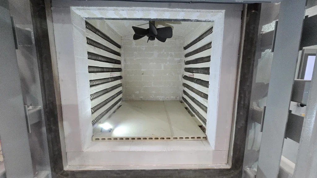
- Side heating
- Top and bottom heating
- Left and right heating
- Surrounding heating
- Bottom auxiliary heating
- Multi-side heating
- Multi-zone distributed heating
The correct arrangement depends on the furnace and application.
(2)Use Top and Bottom Heating for Flat Loads
For flat materials, substrates, plates, trays, and layered products, side heating alone may not always provide the best temperature distribution.
A top-and-bottom heating structure can expose the upper and lower surfaces of the load more directly to the heat source.
This configuration is useful for applications such as:
- Ceramic substrates
- Electronic ceramics
- Flat metal components
- Silicon carbide materials
- Semiconductor materials
- Powder trays
- Thin plates
- Sintering trays
For example, a vacuum atmosphere box furnace can use heating elements distributed in both the upper and lower furnace planes to establish a bidirectional heating field.
This reduces dependence on heat transfer from only the furnace sides and can improve the uniformity of flat loads.
(3) Use Multi-Zone Temperature Control
As furnace chamber size increases, maintaining uniform temperature with a single heating zone becomes more difficult.
This is especially true for:
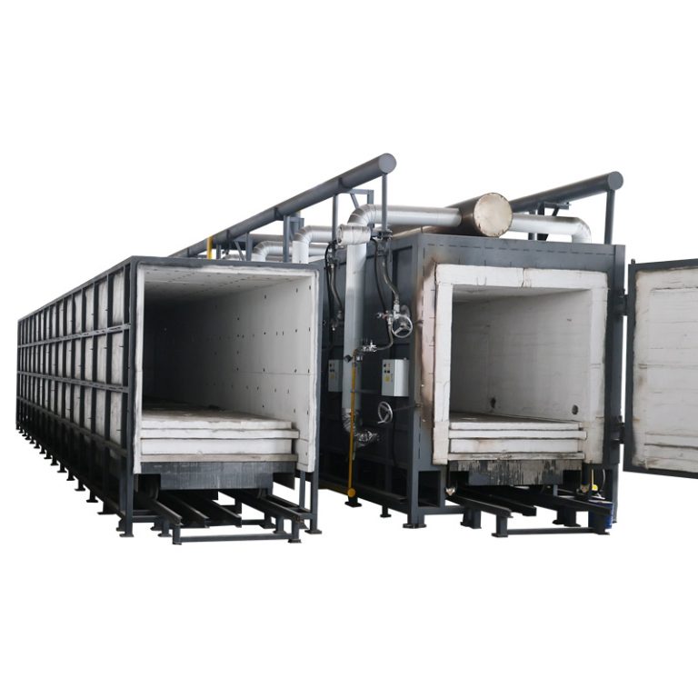
- Large box furnaces
- Lifting furnaces
- Pit furnaces
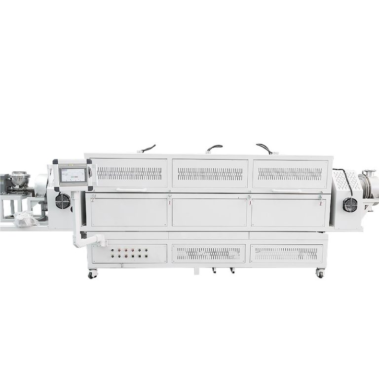
- Long tube furnaces
- Continuous furnaces
- Large vacuum furnaces
Instead of controlling the entire furnace as one zone, divide it into several independently controlled heating zones.
For example:
Zone 1 → Left
Zone 2 → Center
Zone 3 → Right
Zone 4 → Bottom
Each zone can compensate for local heat losses independently.
If the furnace door area loses more heat, that zone can receive more power.
If the center becomes hotter than the edges, the control system can reduce center-zone output.
This creates a more balanced temperature field.
(4)Increase the Number of Heating Zones for Large Furnaces
Large furnace chambers generally require more sophisticated temperature management.
A small laboratory box furnace may perform well with a relatively simple heating arrangement.
A large industrial furnace may require:
- 3 heating zones
- 4 heating zones
- 6 heating zones
- 9 heating zones
- Or more
The correct number is not determined by furnace volume alone.
It depends on:
- Chamber length
- Chamber width
- Chamber height
- Door position
- Load geometry
- Heating-element arrangement
- Heat-loss distribution
- Temperature-uniformity target
For example, a deep vertical pit furnace may experience a significant temperature gradient between its upper and lower sections.
Dividing the furnace vertically into multiple independently adjustable zones allows each section to compensate for its own heat loss.
(5)Position Thermocouples Correctly
The temperature controller can only respond to the temperature information it receives.
If a thermocouple is installed in an unrepresentative position, the displayed temperature may not accurately represent the load temperature or overall furnace temperature.
Thermocouple placement should consider:
- Distance from heating elements
- Distance from chamber walls
- Distance from the load
- Furnace geometry
- Air or gas circulation
- Number of heating zones
For multi-zone furnaces, multiple temperature-measuring points may be required.
A large furnace may use separate thermocouples for:
- Left zone
- Right zone
- Center zone
- Bottom zone
or multiple vertical positions in a deep chamber.
Each sensor provides feedback to its corresponding control loop.
(6)Optimize PID Temperature Control
A well-designed furnace still needs an appropriate temperature-control strategy.
PID control continuously adjusts heating output according to the difference between:
Set Temperature – Measured Temperature
Poor PID tuning can cause:
- Temperature overshoot
- Temperature oscillation
- Slow stabilization
- Repeated heating and cooling
- Inconsistent process temperatures
Modern industrial furnaces may use:
- PID control
- Auto-tuning
- Multi-zone PID control
- Programmable heating curves
- Independent zone control
- PLC-based coordinated control
For demanding applications, each heating zone can use independent feedback while the overall system coordinates all zones.
(7)Reduce Heat Loss Through the Furnace Structure
Temperature uniformity is not determined only by heating elements.
Heat loss also matters.
Common heat-loss areas include:
- Furnace door
- Chamber corners
- Observation ports
- Atmosphere ports
- Exhaust ports
- Thermocouple openings
- Furnace roof
- Bottom loading structure
If one area loses significantly more heat than another, it may create a local cold zone.
Improve insulation using appropriate:
- Ceramic fiber
- Alumina fiber
- Refractory boards
- Insulating bricks
- High-temperature insulation layers
The insulation system should match the furnace’s operating temperature.
(8)Improve Furnace Door Sealing
The furnace door is often one of the largest sources of localized heat loss.
Poor door sealing may cause:
- Cold zones near the entrance
- Higher power consumption
- Longer recovery time
- Atmosphere leakage
- Temperature fluctuations
Inspect:
- Door insulation
- Sealing surfaces
- Hinges
- Locks
- Refractory condition
- Mechanical alignment
For atmosphere or vacuum furnaces, sealing is even more important because leakage can affect both temperature and process atmosphere.
(9) Optimize Load Placement
Even a well-designed furnace can develop temperature differences if it is loaded incorrectly.
Avoid placing the entire batch:
- Against one furnace wall
- Directly beside heating elements
- Directly against the furnace door
- In one concentrated pile
- With no space between components
Instead:
- Distribute the load evenly
- Maintain appropriate spacing
- Keep the load within the qualified working zone
- Avoid blocking heat-transfer paths
- Use suitable trays or fixtures
The goal is to allow heat to reach all surfaces as uniformly as possible.
(10)Avoid Overloading the Furnace
More products per batch may appear to increase productivity, but excessive loading can reduce temperature uniformity.
A dense load can:
- Block radiant heat
- Restrict gas circulation
- Increase heat-up time
- Create cold areas inside the load
- Increase temperature recovery time
For example, the furnace controller may display:
1000°C
while the center of a densely packed load has not yet reached the required process temperature.
This is why furnace temperature and actual load temperature should not automatically be treated as the same value.
(11)Control the Heating Rate
Heating too quickly can temporarily increase temperature differences inside the furnace.
The heating elements may reach high temperatures rapidly while:
- The furnace walls remain cooler
- Heavy workpieces heat slowly
- The load center lags behind the surface
- Different zones respond at different rates
For demanding processes, use a programmed heating curve.
For example:Room temperature → controlled ramp → intermediate hold → controlled ramp → process temperature → soak
An intermediate holding stage can allow the temperature field and load temperature to equalize before further heating.
(12)Improve Atmosphere or Air Circulation
In some furnace designs, gas movement can improve heat transfer.
This is especially relevant for:
- Low- and medium-temperature ovens
- Atmosphere furnaces
- Drying furnaces
- Certain heat-treatment furnaces
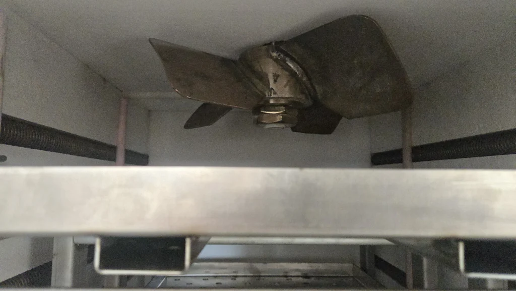
Fans or controlled gas circulation can help reduce stagnant hot and cold regions.
However, forced circulation is not suitable for every high-temperature furnace.
At very high temperatures, heat transfer may rely primarily on radiation, and fan materials may not tolerate the operating environment.
Therefore, circulation design must match the furnace temperature and process atmosphere.
(13)Balance Furnace Pressure and Gas Flow
In atmosphere furnaces, gas inlet and exhaust design can also affect temperature distribution.
If cold protective gas enters one location at excessive velocity, it can create a local cooling effect.
Poor exhaust distribution can also produce uneven atmosphere flow.
Consider:
- Gas inlet position
- Number of gas distribution points
- Flow rate
- Exhaust position
- Furnace pressure
- Gas preheating where appropriate
The objective is to avoid a concentrated cold gas stream directly impacting the workpiece.
(14) Check Heating Element Aging
Heating elements do not always age uniformly.
Over time, some elements may:
- Increase in electrical resistance
- Produce less effective heating
- Become damaged
- Develop poor electrical connections
- Operate differently from neighboring elements
This can create localized cold zones.
Regularly inspect:
- Heating elements
- Electrical connections
- Resistance values
- Power output by zone
- Current by zone
For multi-zone furnaces, comparing electrical parameters between zones can help identify abnormalities.
(15)Calibrate Temperature Sensors Regularly
A furnace may appear to have a temperature-uniformity problem when the real problem is measurement error.
Thermocouples can drift with:
- High-temperature exposure
- Long operating time
- Contamination
- Thermal cycling
- Mechanical damage
Regular calibration helps ensure that the temperature-control system is receiving accurate data.
Check:
- Control thermocouples
- Monitoring thermocouples
- Reference instruments
- Data acquisition systems
For critical applications, temperature mapping should be performed using calibrated sensors.
3.How Does Multi-Zone Control Improve Furnace Temperature Uniformity?
Consider a large furnace divided into four zones:
| Heating Zone | Typical Location | Function |
|---|---|---|
| Zone 1 | Left | Compensates left-side heat loss |
| Zone 2 | Right | Compensates right-side heat loss |
| Zone 3 | Center | Controls central working zone |
| Zone 4 | Bottom | Compensates bottom heat loss |
If the bottom of the furnace is colder, the bottom zone can receive additional heating power without overheating the upper chamber.
This is much more precise than increasing the power of every heating element simultaneously.
Multi-zone control is therefore especially valuable for:
- Large furnace chambers
- Tall furnaces
- Long furnaces
- Heavy loads
- Strict temperature-uniformity requirements
4.Temperature Control Accuracy vs. Temperature Uniformity
These two specifications are frequently confused when purchasing a furnace.
Temperature Control Accuracy
This refers to how accurately the controller maintains the temperature at the sensor or control point.
For example:
Control accuracy: ±1°C
This does not automatically mean the entire chamber is within ±1°C.
Temperature Uniformity
This refers to the temperature difference across a specified working zone.
For example:
Furnace uniformity: ±5°C within the specified working zone
Therefore, when comparing furnace quotations, always ask for both:
Temperature control accuracy + temperature uniformity
and ask the manufacturer to specify the conditions under which the uniformity value is measured.
III.Furnace Temperature Uniformity Troubleshooting Table
| Problem | Possible Cause | Recommended Action |
|---|---|---|
| Front colder than rear | Door heat loss | Improve sealing or front-zone compensation |
| Bottom colder than top | Insufficient bottom heating | Add or adjust bottom heating zone |
| Center too hot | Excess center power | Reduce center-zone output |
| Upper/lower difference | Poor vertical zoning | Add independent vertical heating zones |
| Temperature oscillation | PID settings | Retune PID parameters |
| Load center remains cold | Excessive loading | Reduce load density or extend soak time |
| One side remains cold | Heating-element problem | Inspect elements and electrical connections |
| Uniformity worsens over time | Sensor/element aging | Calibrate sensors and inspect heating elements |
| Atmosphere furnace has local cold spot | Gas flow too concentrated | Optimize inlet and exhaust distribution |
IV.Conclusion
Improving temperature uniformity in an industrial furnace requires coordinated control of the entire thermal system. Heating-element distribution, multi-zone temperature control, thermocouple placement, PID settings, insulation, door sealing, load arrangement, heating rate, and atmosphere flow can all influence the final temperature field.
For small chambers, a well-designed heating-element arrangement may be sufficient. For large, long, or deep furnaces, multiple independently controlled heating zones can compensate for local heat losses and temperature gradients more effectively.
Click “Request a Quote” to get a customized solution.
V. FAQ
1. How can I improve temperature uniformity in an industrial furnace?
Optimize heating-element distribution, use appropriate multi-zone temperature control, improve furnace insulation and sealing, position thermocouples correctly, avoid excessive loading, control the heating rate, and perform regular temperature mapping and sensor calibration.
2. What is the difference between temperature accuracy and temperature uniformity?
Temperature control precision refers to how well a controller maintains the temperature at the specific point where it is being measured, while temperature uniformity refers to the extent of temperature variation throughout the entire effective working zone. A furnace with a temperature control precision of ±1°C does not necessarily have a temperature uniformity of ±1°C within its chamber.
3. Why are multiple heating zones used in large industrial furnaces?
Large chambers can develop different heat-loss conditions at the top, bottom, sides, center, or door area. Independent heating zones allow the control system to adjust power locally instead of increasing or decreasing the output of the entire furnace.
4. Does increasing furnace power improve temperature uniformity?
Not necessarily. While increasing the total power will speed up the temperature rise, it may also exacerbate existing hot spots. To achieve better uniformity, you generally need to focus on the arrangement of heating elements, zoned control, temperature monitoring, thermal insulation, and the management of how the material is loaded.
5. How do I know how many temperature-control zones my furnace needs?
There is no standard answer as to how many temperature zones a furnace should have. It depends on a variety of factors: the size and shape of the furnace chamber, the volume of the load, the operating temperature, the arrangement of the heating elements, and the required level of temperature uniformity. If a furnace chamber is large, long, or deep, it will naturally require more independently controlled temperature zones; for a small laboratory furnace, however, such a setup is unnecessary.
Supplier
Luoyang Anjing Intelligent Equipment Co., Ltd. is an enterprise dedicated to the research, development, production, sales, and technical services of heat treatment equipment such as high-temperature electric furnaces. We produce laboratory, vacuum, industrial, and medium frequency furnace, covering a temperature range from -100℃ to 2600℃, serving industries such as new energy, semiconductors, and advanced materials. We can provide customized solutions based on specific atmosphere, ultra-high temperature, and intelligent control system requirements. Please feel free to contact us if you are interested.